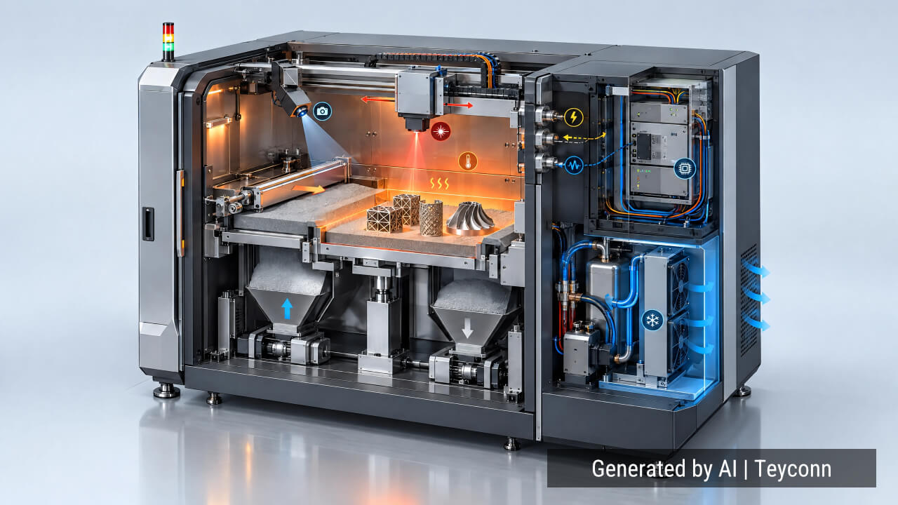
On the electrical drawing, an industrial additive manufacturing machine looks simple: temperature sensors, heaters, motors, encoders, a recoater, a camera, each a line to a connector symbol. In the machine, those connection points live in very different worlds. A sensor interface beside a heated polymer build chamber faces heat and long thermal soaks. On a metal powder bed machine, an interface may sit near a powder-filled process chamber under controlled gas or vacuum. A motor cable on a moving gantry flexes on every pass. Connector selection has to follow the local environment and the circuit’s function rather than the machine’s label.
1. Problem / Context: There Is No Single “AM Build-Chamber Environment”
ISO/ASTM 52900 treats additive manufacturing as a family of processes, and the environments they create differ more than machine labels suggest.
In material extrusion, many industrial platforms use actively heated build chambers to manage cooling and warpage; how hot, and whether the chamber is heated at all, depends on the machine and material. Two systems built for different polymers can place very different demands on their cabling. Vat photopolymerization differs again: some architectures control resin temperature to manage viscosity, recoating or curing behaviour, others do not.
Metal powder bed fusion adds a further case. Laser-based systems commonly run in a sealed chamber under a controlled inert-gas atmosphere, often with recirculating flow; gas choice and residual-oxygen requirements depend on the material and machine. Electron-beam systems differ, running under vacuum. In either case, how power and signals cross the chamber boundary follows from the atmosphere and pressure involved.
Post-processing equipment, from powder recovery to heat treatment, adds further environments with distinct thermal and contamination loads.
Define the local environment first. “Inside the printer” is not one environment.
2. Why It Matters: What Happens If These Factors Are Overlooked
Heat: Move the Connector Away When You Can
The first question about a hot zone is whether the interface needs to be there at all. Where the layout allows, run suitable high-temperature wiring through the hottest region and terminate in a cooler service zone behind a thermal barrier. Moving an interface away from heat is often a better decision than specifying a more exotic connector.
Where an interface must sit in elevated temperature, heat acts on the complete chain: insulation, housing, elastomer seals, cable jacket and contacts. It reduces the connection’s thermal margin and can accelerate the ageing mechanisms that raise contact resistance over time. Current-carrying capability falls as ambient temperature climbs, so contacts that are comfortable beside the electronics cabinet may need derating near a heated chamber. The practical limit is set by the lowest-rated element in that chain; a high-temperature housing achieves little if the standard jacket behind it softens first. Governing values sit on specific datasheets.
Powder Changes the Design Problem
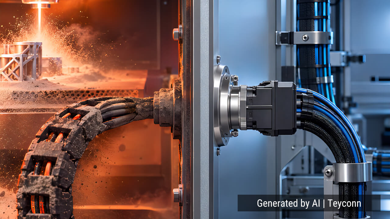
Fine powder is an aggressive contaminant. It migrates into threads, hinge gaps and contact cavities, jams locking mechanisms and makes every service intervention a cleaning task. In metal powder bed fusion the chamber is also an atmosphere or vacuum boundary, so everything passing through it must preserve that boundary between maintenance intervals.
Sealed feedthroughs can carry power and signals through the chamber wall, keeping detachable interfaces outside the process atmosphere, where they can be mated, inspected and replaced without opening the chamber. Where connections sit near powder handling, geometry matters: avoid open upward-facing cavities that collect powder, and route regular mating to designated service areas.
Ingress protection ratings need careful reading here. An IP class under IEC 60529 describes an enclosure’s degree of protection against solid foreign objects and water under defined test conditions; it does not establish chemical compatibility with metal powders or suitability for combustible-dust hazards. Those hazards, linked to certain metal powders, are handled through the machine-level risk assessment and applicable regulations. Where they affect an electrical interface, connector and feedthrough selection must follow the resulting requirements.
Motion and Cable Mechanics
AM machines move in disciplined, repetitive ways: platforms stepping through layers, recoaters sweeping the bed, gantries carrying print heads. An electrically correct interface can still fail because the cable is flexed in a way it was never built for.
Static and continuous-flex cables differ internally, and the difference matters wherever motion is continuous. Dynamic bend radius and flex-cycle capability must come from the cable manufacturer’s specification; no universal ratio covers every construction.
The cable-to-connector joint is a separate problem. Strain relief should keep tensile and bending loads away from the termination, exit geometry should suit the direction of travel, and support spacing should keep flexing in the designed bend region instead of at the backshell. Cable and connector have to be engineered as one assembly; no connector compensates for a conductor that fatigues just behind it.
EMC Is Easy to Overlook
Interference sources are plentiful and ordinary: servo drives, switching power supplies, heaters switched by power electronics, high-current motor wiring routed near signal lines. Poor shield continuity or careless routing can couple that noise into encoder or sensor circuits, where it appears as position jitter or intermittent errors that are tedious to trace.
Where layout allows, keep noisy power paths physically separate from sensitive signals instead of sharing long parallel runs. Shield termination deserves the same deliberation: at higher frequencies a broad, low-impedance connection can be advantageous, but the right scheme depends on the machine’s overall EMC and grounding design.
A Representative Failure Scenario
Consider a representative failure in a heated, moving subsystem. A machine develops intermittent temperature-sensor alarms during long builds. The sensor tests correctly and is replaced; the alarms return. They correlate with carriage movement and with the later stages of builds, after hours of thermal soak. Inspection eventually shows the cable flexing at the connector backshell on each carriage pass, its insulation stiffened by heat, the detachable interface sitting too close to the heated zone.
The fix required no better sensor: the interface was relocated behind a thermal barrier, strain relief was added so bending no longer reached the contacts, and a cable suited to the actual movement and temperature was specified. The electrical specification had been correct; the mechanical and thermal installation had not.
3. How to Select
A single machine mixes circuits with very different priorities. Temperature sensors carry low-level signals where contact stability matters more than power. Encoders and position feedback need signal integrity and often shielding. Motor lines carry current through vibration and rapid direction changes. Heater circuits are governed by current capacity and thermal derating. Cameras and industrial Ethernet add data integrity and shield continuity.
Before choosing a connector family, ask: What process is this, and what is the actual local temperature at the interface? Is the connection inside the process atmosphere or outside it? Can powder reach it, and can it be cleaned? Does the cable move continuously? What circuit does it carry, what voltage and current, and is shielding needed? How many contacts does it need? How often will technicians disconnect it, and where?
Only once these conditions are defined do connector family, materials, locking method, cable construction and size follow sensibly.
The Drawing Symbol Is Simple
AM equipment does not impose one environment on its electrical interfaces; it imposes several, and no single connector sees all of them. Reliable design separates the thermal, environmental, mechanical and electrical requirements of each interface, then selects the connector as part of the whole machine architecture. The drawing symbol is simple. The conditions behind it rarely are.
About the Author
Dennis Chiang is founder and technical engineer at Teyconn, where his work focuses on industrial connectivity, cable assemblies and connector reliability for automation, machinery and demanding industrial environments, including additive manufacturing equipment.
Website: Teyconn website
LinkedIn: Dennis Chiang on LinkedIn